
Raspberry Pi Cover Making and Functional exploration

In the last term I used a combination of raspberry pi and arduino to create a successful project based on the concept of ‘controlling time’. I made extensive use of 3D animation techniques and used code to connect and work with devices. After the last project, I made a concerted attempt to understand the code and the various digital hardware in more depth to find more possibilities. I tried a number of approaches, but they always left me with a superficial understanding rather than a deeper understanding of how they work. So I set myself a short, personal little project of building a wooden case for the raspberry pi and making it work like a normal computer, if not more conveniently. Unfortunately, as this was only for learning more about the device, and as it was only a private endeavour and a lot of work, I didn’t keep a record of the process of making it.
In the picture on the left, the raspberry pi I used in my last project is shown on top and the modified raspberry pi is shown below. It is also a modular audio device that can be used as an audio player for other devices when connected to an external audio player using an aux cable, with the left and right sides removable to reduce its size, or as a rechargeable battery.Through this project I was able to learn what the raspberry pi can do, what devices can be connected and how to connect them. Through this project I was also able to gain insight into most of the development boards that share the same principle, such as the esp32, esp32 s2, esp32 s3, Arduino MEGA 2560, Arduino Micro, Arduino Leonardo, Arduino Pro-Mini, Teensy 4.0, raspberry pi series, etc.
Stage3 Idea

By extending the functionality of the raspberry pi, I came up with two ideas for creations (which have since been superseded). Also they can both be realised by working together between multiple Arduinos.
Idea 1:
Two arduino’s are used, one connected to a camera and one to a monitor, the camera and the monitor are on either side of the wall. The display shows the face captured by the camera. The other arduino is connected to a glove sensor that can be worn to sense the dynamics of hand movements. The arduino is also connected to a robotic hand that simulates the movement of a human hand.
Scenario Scenario:
In my imagination, I have the idea of two people interacting through my device. Two people can only feel each other through one sense.
Idea source:
We are now in an age where communication is extremely easy. We can talk to someone on the other side of the world with the press of a few buttons on our mobile phones. At the press of a few keys we can buy goods from the other side of the world and have them delivered to our homes within days. But in an age where communication is so easy, it seems we have lost some of our ability to be touched. To some extent, I think we always remember the past because it was extremely powerful, and because we have produced so much of it, we have become numb to it. And to recapture it requires renewed contact, which is extremely unlikely in such a convenient age. So this work was made to show that mechanical contact is no substitute for real contact.
Idea2:
This idea requires an arduino with more interfaces to be implemented. The arduino would need to be connected to several small LED displays, each with an eye and animated by mathematical calculations of its random movements. An ultrasonic distance detector would also be mounted on top to detect the distance between the viewer and the wall
Scenario Scenario:
In the absence of an audience, all screens display a constant random rotation of the eyes. When the ultrasonic rangefinder detects the presence of an audience, all eyes are fixed on the audience
Idea source:
As soon as I started learning to use arduino and code, I started to realise that the personal information and behaviour we value most was not as safe as we thought. It’s as if we’re being watched by some invisible force. It doesn’t have to be a specific person or thing without me knowing what it is, and he is even manipulating our behaviour to some extent. For example, precise push ads, certain items some people can buy at a lower price than others, etc. It all seems to indicate that our every move is being recorded, and that this person who is recording us is not even an angel but a thing of our own creation.
Classmate’s random servos

First, I cut off the original connection (female) of the servo and replaced it with a connection (male) that can be connected directly to the breadboard and Arduino
Using the library that comes with the Arduino IDE, I have been able to get the servo to operate at the angle and dwell time that I set.
VIEDO: https://youtu.be/ej0IKbxwQ5c
After I had connected the two servo’s to the arduino, the really difficult part was to pick one at random and get it to rotate according to my settings
In the code I wrote a random number of either 1 or 2 to select the servo to run according to the random number. If the random number selected is the same as the last one, it is reselected.
VIDEO: https://youtu.be/iGoYQpLZltI
After I finished the random mode, I made an all-off mode and an all-on mode and modularised them in the code so that I could adjust the modes at will
After that, I found it cumbersome to need to upload the code for a particular module separately, so I decided to integrate them together and try to control the modes with buttons
VIDEO(pic.1): https://youtu.be/w6FOT7k3ycw
VIDEO(pic.2): https://youtu.be/2LHirY7AjbU

As I have modularised the code, I can always add the number of servos by adding a servo function to each mode. However, there are often errors such as unresponsive keys or instructions being read multiple times. This is due to the fact that the arduino is part of a small computing unit at its core and cannot run two events at the same time, I just use an interrupt function to interrupt the operation it is doing, so there is no way to avoid errors. A second arduino would be needed if I wanted to deal with this problem.
VIDEO: https://youtu.be/It4MABPGfBg
To reduce its size, I soldered a 5v connector so that I could connect the power supply directly through the colour of the wire and no longer need a power breadboard
For the mode button, I created the circuitry for the button directly by soldering a PCB board myself, thus eliminating the need for a breadboard for the button.
For the mode button, I created the circuit for the button directly by soldering a PCB of my own, which also eliminated the breadboard for the button.
This project gave me a new idea for an electronic bug that moves by means of a small servo. By connecting several servo’s and making them work together to produce a bug state.
Worms have a strange meaning in Eastern culture, they are constantly writhing as if they are struggling. This struggle is a desire to transcend the infantile. In fact, as a child I was very fond of a worm called a Trypoxylus dichotomus, which is so strong that it can lift more than several times its own weight. This also represents the ability of adults in Eastern culture. And what I am going to make is what they looked like as larvae.

As the rudder units in my work are slowly being completed, my code is slowly becoming more complete. But my classmates kept coming up with new ideas and needed me to change many parameters in the code. For example, the number of servos used, the arduino pins they need to be connected to and many other parameters. In order to cope with this problem and to allow her to make changes to the code without me, I made the final optimisation of my code.
In the code above, I have used an array to organise all the arrays directly into a servo group. In this code, the user can change the six parameters at the beginning of the code to allow different numbers of servos to cycle as required. The previous button interrupt function to change the mode of operation of the servos will still work, but it will still make the overall operation less stable and I would still recommend that the user removes the interrupt function section if the button is not used.
Code Reference Video: https://youtu.be/kUHmYKWwuWs
After testing, the code successfully runs all the functions I have set up with no bugs, and the number of servos, operating modes and angles can be changed by modifying the 6 parameters I have indicated.
Bugs and Dynamics

During my childhood, such bugs would often intrude into my home and I would often play with them and try to keep them. Because they eat aphids and have a very positive effect on agricultural production, they were also often depicted in our primary school textbooks in a very positive light. Of all the bugs, the silkworm from the south of the Yangtze River is very popular with the Chinese. It does not only produce the silk needed for silk. It is also due to the fact that it can change through its pupa into a moth that can fly. This animal, which had difficulty surviving in the early stages and evolved itself through hard work, was often favoured by the Chinese. In Chinese cultural philosophy, the Chinese refer to this process as “building up” and “enduring humiliation”.
With the creation of the random switch, the new idea is to simulate the dynamics of this bug by means of a tiller.
Not only did the Chinese show a fondness for bugs, but the ancient Egyptians also had a different kind of admiration for them, especially for beetles. This beetle tended to carry the dung of some animal and lay its eggs in it. Khepri, one of the Egyptian gods, had a beetle head.
The Trypoxylus dichotomus is commonly found in China, Japan and South East Asia and is a pet for some people due to its ornamental presence. In Japan, it is one of the insects that children must know. As they are relatively easy to survive and have a short dormancy time, many adults also use them as pets and try to obtain more Trypoxylus dichotomus by keeping them. They are so strong that they can carry up to 850 times their own weight and are also known as “insect Hercules”.
When I was a child, these were the kind of insects I would have liked to have kept.
In many games, films and animations, Trypoxylus dichotomus are often one of the most valuable materials, and they have been the inspiration for many animated images and creations.
In the game, The Legend of Zelda Breath of the Wild, the Trypoxylus dichotomus is a very valuable material that can be used to make very powerful items. One of the most popular aspects of the game is the fact that the travelling merchant Terry Day will ask to exchange the Trypoxylus dichotomus with the protagonist if he finds one on him.
Trypoxylus dichotomus also exist in the Animal Mori Friendship Club, and if the protagonist captures a Trypoxylus dichotomus and donates it to a museum, its habits and specific information will be displayed in the game.
In Japanese anime such as, for example, Silver Soul, Detective Conan, Crayon Shin-chan, Digimon, Doraemon, One Punch Man, etc. Trypoxylus dichotomus appear frequently and they either represent strength or a male figure. At the same time, they also represent the joy that comes with adventure.
In some Japanese TV series, Trypoxylus dichotomus have become the inspiration for some of the costume designs. In the context of film and television dramas, the Trypoxylus dichotomus often represents justice and fairness again, as well as the strength and power to carry out justice.
While the inspiration for my work was the Trypoxylus dichotomus, what I wanted to do was the larvae of the Trypoxylus dichotomus. Using this to represent a compressed force trying to break free and threatening to explode at any moment, I also wanted to show the psychological state of people in contemporary Chinese society who are constantly suppressing their ignorance of social issues and compressing themselves.

Bionic sculptures are not very common, and the first one I saw was located near the Oil Can Art Centre in Shanghai. There were some awnings there, but they were put together in a similar way to knitting. They do not provide much shade, but they are very reminiscent of mushrooms. Especially the shadows they create. But in reality the whole sculpture is just a flat surface above. The sculpture does not give the viewer the impression of a creature in terms of its appearance, but rather in terms of the feeling it brings.
For me, this was my first introduction to bionic sculpture. What I wanted to try was not to start from the shape of the sculpture or the feeling that the shadows gave. Rather, I wanted to try to simulate the movement of a living creature.
In everyday life we often see this same Beetle car on the street. It has had this rounded appearance, similar to the Beetle, since its interview in 1938. In modern times, the shape of many cars has slowly become more rounded. This car is also popular with car enthusiasts for its appearance and performance.
The Russian artist Roman Booteen uses coins as the raw material for many of his engravings. Many of his carvings are based on animals or plants and the finished images are very beautiful. In addition to this, his works are mechanically linked to the images on the outside, so that when a button is pressed on the coin, the design moves or performs certain actions. These movements are often designed to simulate the movements of these animals or plants in the real world. Of all its creations, this one, based on a beetle, is so popular that many jewellery makers often reproduce it using different materials and sell it for a price.
Chinese sculptor Xiao Di has produced five large movable sculptures based on Chinese mythological creatures: a horse, a unicorn, a cow, a white tiger and a grizzly bear. Although these sculptures are very bulky and do not move very sensitively. However, they can simulate the movements of the animals. One of the things I don’t like is that they already look like the animals and attract commercial and capitalist attention as a way to promote them, so I don’t want my work to look like the animals.
Anika Yi created a work based on a jellyfish at tate modern in 2021, which had a very dreamy feel to it, and fortunately I saw it in person in 2021.
Strandbeest by Dutch artist Theo Jansen is one of my favourite pieces of sculpture. It gives me an extremely dreamy sense of stepping into reality, and unlike Anika Yi’s sense of transporting the viewer into childhood, it is more like taking one down a rabbit hole. This way of creating a work that simulates the movement of a creature rather than the shape of an animal raises the question of whether a certain shape is a necessary condition for a certain written movement.
Just a few days ago, I saw that the work had begun to fly in the air. In the pictures the sculpture looks a bit like a Chinese kite.
It uses only wind power, and because of my shortage of time to create it, I had to choose a simpler and quicker way to achieve a similar effect. However, I will still try this way of creating a sculpture that only simulates the movement of the animal and not its shape.
Space engineering and applications

As my final work contained animal forms with mechanical dynamics, I spoke to a friend of mine who studies space engineering. After I expressed my idea, it showed me the Japanese university student robot sumo wrestling competition, in which the video showed their robots moving very quickly. It was also true that the rules of sumo wrestling could be used to compete between robots. This was something that surprised me a lot. He thought it would be almost impossible for me to simulate the pose of an animal with an arduino, especially for someone like me who has little development experience. He thought that I could change the form but achieve the same purpose of the robot like the sumo robot in the video.
Afterwards, I spoke with my friend on a deeper level. I said that the point of my work was more about whether I could try to use simple servos to simulate six directions of rotation as much as possible, which could reduce the cost of learning and building to a large extent. (https://youtu.be/mS-L2fpV1Is )
Some people are also working on small snake robots, and their projects look more like improvised versions of NASA projects. So the idea I’m trying to arrive at is a very possible one, but without a tutorial. (https://youtu.be/abMJAapfmeo )
In addition, someone has also created MorpHex, the robot from the game Portal, which is a spider-shaped robot that can also turn into a ball. It also uses a lot of servos to accomplish a flexible trajectory of movement. The method is very simple, but to achieve worm-like writhing it is necessary to find a way to reduce the distance between the axes of rotation of the servos even more. But this already gives me an idea of what is possible. (https://youtu.be/OI4OiKNEixc )
My friend then suggested a project that NASA was working on, in which I could see that they were working on a snake-like robot. These robots are mainly used in terrain exploration and space exploration projects. But I found one of the things that was very different from what I had in mind. The robots they were working on tended to present a group that could only rotate in four directions, and each axis of rotation was very far apart. What I wanted to do was to minimise the distance between the axes of rotation in a group to make the whole more flexible. The amount of work involved was definitely not something that could be done by one person in two months, nor was it applicable to my idea, so I decided to abandon it. But I did get some ideas about joints. One joint is a servo unit, and by connecting multiple servo units together I could create the form I wanted. And the worm doesn’t seem to move much differently from the snake, except that the worm is a bit fatter. (https://youtu.be/ifCIDT4X9AM )
Random Worm

To complete my random bug, I chose to use 10 small SG90 servos for my experiments. Although these servos often fail to return to positive or are underpowered, they are low cost and are very suitable for experimentation. In order to experiment without any other wires or breadboards, I first removed the device connections and converted them to JST male ports so that they could be connected directly to the Arduino, and if they needed to be soldered directly to the development board, this could be done more easily and securely. However, as there is only one 5V port on the Arduino, I still need to use the power breadboard.
Illustration of the servo matrix circuit diagram:
The materials for testing need to be connected according to the circuit diagram on the left. Each servo needs to be connected to Arduino pins 0 to 13 to output the PWM signal correctly. Pins 0 and 1 are for data communication and are often used for communication between multiple arduinos, so I need to keep these two pins for the future as I may use multiple arduinos and need to keep them synchronised.
VIDEO:
Code description:
Where this code differs from the previous code is that in this code I have created an array directly. Each number in the array is used to represent the entire servo matrix. When an operation needs to be performed on a single servo, the selection of the array is straightforward. The code is also much easier to modify, simply changing the numServos and the corresponding pin numbers to ensure that the code will work.
Shortcomings and parts to be modified as shown in the video:
In the video, the servos are working properly on the first trial, which shows that the code is ready to operate the arduino to issue the correct commands to the servo array and perform the correct operations. However, on the second experiment, all the servos appear to be jerking out or not moving, while the lights on the arduino appear to be flickering. I think this situation is most likely due to insufficient power supply. I have since removed servos 8-10 and this condition persists, but in my previous experiments the arduino was able to supply 7 servos. I eventually solved the problem by plugging in another 5V power supply.
After searching through various sources I found the current information for the servos and the arduino and calculated the power consumption required for 10 servos.
Current supply calculation and solution:
According to the official documentation of the SG90(https://images-na.ssl-images-amazon.com/images/I/61jUf7Q-0uL.pdf )can find:
At 4.8v, the SG90 requires 6mA of current at standstill and approximately 400mA of current in the case of rotation.
Current required for a stationary SG90:
Total current required = operating current of individual servos * number of servos
Total current required = 6mA * 9 stationary servos = 54mA
A moving servo delivering 9G of power would require 400mA of current, if only its rotation is required, it is estimated that 200mA of current is required.
In total, approximately 254mA is required to keep all the servos running.
It has been pointed out in the official Arduino discussion community that the Arduino’s 5V interface can output a maximum of 200mA. (https://forum.arduino.cc/t/maximum-current-draw-on-5v-and-vin-pins/50417 )
In this case, 10 servos are just beyond the Arduino’s power supply limit.
Considering that I will most likely replace it with the more power hungry MG996 servos later, I will add a PCA9685 and connect another power supply to the finished product as an additional power supply.
Summing up:
The problem I solved in this section was to simplify my code to make it easier to change some of the data in the code in the future, so that I can easily communicate with multiple Arduino’s and check the progress of the run. In addition to this, I have also identified the problems that can occur when running all the materials and found solutions to them. I have also implemented the initial module to make the servo do what I want it to do, the next thing I need to think about is incorporating random numbers into this code and allowing the servo to move randomly.

After I ordered a new servo and power board, I had to continue using the SG90 to continue refining my code. In this part I needed to modularise the whole bug, with one joint for every three servos (the problems with this were discovered later on). Afterwards the random numbers were intervened into the previous code.
Video:
Initially, I did not include delay(150); and caused the three servos to twitch, which was caused by the Loop part of the Arduino running too fast, so I added a wait time to give the whole device and the human eye enough time to react to the whole course of action. In the end, the whole device did look more like a robot performing a dance movement.
During the test, the entire servo set tilted, due to the lack of power in the servos I was using, which I thought would be resolved later. However, I began to feel another concern, and that was whether the topmost rudder would strike the table if the whole piece was built.
Video:
To test my suspicions, I assembled all 10 servos and indeed the situation I feared occurred. To do this I adjusted the rotation angle from 0-180 degrees to 30-150 degrees so that the whole set of servos rarely knocked on the table, and I also made a small optimisation to the code so that I did not need to change the number of servos in the body of the code.
This caused one of the servos to break as it could not carry the load due to the overwhelming number of servos in the whole piece. But the code was successful. Until now, the code for how the servos are connected to each other and the random movement of the servos has been completed. The next step is to wait for the material to be delivered before proceeding.
Video:
After testing the code for the random movement, the connections of the servos became detached. This was caused by the fact that I had used nanotape as a temporary assembly solution, which is suitable for smooth surfaces but comes off easily when attaching objects with rough surfaces, so I needed to think of an alternative method of attachment.
In order to find out how I could solve the fixing problem, I found out that there was a Mount on the market that was used to fix the servo. I also found out that most of the servos I will be using and using in my experiments will be used by people to control the directional control servos of drones and RC vehicles. As their function is relatively fixed, this is the only size of mount available in most cases. On top of that, at £8 per mount and I need at least 22 mounts in total, they cost even more than the servos themselves, so they are unlikely to be the way I use to hold the servos. But if I were to attempt to build a drone, I would give priority to a professional mount like this
However, taking inspiration from the professional brackets, I might also be able to use these coner brackets for furniture as a way of attaching my servos but I’m not sure if they are the right size for this piece but they cost £13 per 80. In the meantime, I will try to find a less expensive way of attaching them. Or try to find out how I can sand them down to the right size. If they are not available, I will use them in my future projects

In order to be able to connect more servos, I chose to use an expansion board called PCA9685, which is designed for servos and connects the control chip via the i2c protocol. It can also be used to supply additional current to the servo via the two green ports on the top.
After reviewing the official documentation and testing, I gave up the idea of using the expansion board as I was not familiar with it.
Although I abandoned the expansion board, I found that the Arduino mega 2650 had more PWM pins than I needed to connect more sensors and servos.
I have since replaced all the servo connectors with JST male connectors, which will make it easier for me to connect them.
Even though the mega has more PWM pins, it only has three 5v pins, which is not enough, so I made two pin to 12 pin wires by soldering, so that one 5v pin can be expanded to six 5v pins.
For each set of servos I made two pin expansion wires. Theoretically, it allows 12 servos to run simultaneously
In addition to this, I made a 2-10 pin extension cable in the same way, so that the power supply for both sets of servos can be connected to this cable and the servos can also be powered from an external power supply via the pins
Through testing, the idea works
After connecting them to the Arduino, they are fully operational
While I was testing to see if I could use both the power supply and the usb connector to power the Arduino, an accident occurred when I used an extra power supply of 24v which fried the Arduino’s voltage management chip. After replacing the chip, it was repaired but the Arduino control chip produced a strange temperature rise. To be on the safe side, I purchased a new Arduino.
Later that night, I developed blisters on my hands, which were caused by the amount of pressing and rubbing I had done when replacing the servo interface. I would recommend using band-aids or gloves to protect your hands during such operations.
When fixing the servos, I used three servos to form a joint that could move in three directions. I also kept their centres of rotation as close together as possible to ensure flexibility
In the process of making the servos, I found that they could not be held together with any kind of double-sided adhesive, even with strong adhesive. So I had to use hot melt glue to hold them in place
After testing, they were very heavy and required me to limit their rotation angle by code, otherwise the two servos would get stuck together
Video: https://youtu.be/ICaBgKvGSiw
As I could feel during my tests that some of the servos were not able to handle the excessive weight, I replaced the 6 large servos on top of each set with 5 smaller ones
After I replaced them, the chattering of the servos stopped
In my search for a better way to manage the power supply I found this expansion board for the inductors which adds a 5v pin next to all the signal pins, which makes everything easier.
In my initial thoughts I also thought about making some small servo units and making them worm like on the ground, so I collected a lot of these disposable e-cigarettes on the street and removed their batteries

Most of these batteries are small and ideal for small projects. After checking the documentation, they are also rechargeable.
Sometimes there is a lot of this furniture waste on the street. Some of them have circuit boards and some other electronic components. I dismantle them and use them in my future ideas.
This sofa has two tweeters, a subwoofer, a class D power amplifier circuit (which has since been damaged) and an audio circuit.
As a surprise, I found a noise filter circuit in it. Of course they will be part of what I may add to my work when I finish the rudder bug
Back to the helm unit, I wanted to glue all the wires to the helm and make everything look neat, so I I used a lot of connecting wires to extend the helm wires
After testing it, it did look a lot neater, but it didn’t seem to have any real significance to the rudder bug I was trying to make, just neatness
After much comparison, I prefer the cluttered feeling, which is closer to the sifi feeling I felt in the research group for stage 2
After a long period of cleaning, I finally finished the job, but some parts needed to be overhauled and replaced due to excessive force
After testing and replacing, I lost a total of 5 small servos. The large servos were not visibly damaged but two had occasional strange chattering but I had spares ready for replacement
After dismantling and overhauling the servos, I found that most of the damage was caused by the wires not being securely attached, which I thought could be fixed by re-soldering. However, I decided to dismantle the 5 servos as spares.
I then found a way to calculate how to get my two sets of servos to rotate in mirror image. What I needed to do was to make the arduino recognise the corresponding single servo in the servo set and the opposite corresponding angle by adding and subtracting.
Mirror rotation test code:
In my work, there are two sets of servos, and in my idea, they are mirror rotating.
Initially, I thought this might be a difficult problem, so I needed to implement it by means of conditional statements, but I found that this might cause the whole code to become too large and thus impossible to upload to the arduino, and also cause the whole code to become inefficient to run. Most importantly, this was the dumbest way to achieve the mirroring effect.
Afterwards, I connected the second set of servo pins to the Arduino in the opposite sequence and was able to implement the whole function simply by adding and subtracting.
Video:
Mirror rotation principle:
Conditions:
Array array = 0, 1, 2, 3, 4, 5
Array = Servo 1, Servo 2, Servo 3, Servo 4, Servo 5, Servo 6
Servos 1, 2, 3 as a group, Servos 4, 5, 6 as a second group
Initial angle: 90
Requirement:
Explain how two arrays of rotate in mirror image in Arduino LOOP
Principle:
If the servo 3 in group 1 needs to be rotated to 30 degrees
The sequence of servos in Group 2 = the array of servos in Group 1 + the number of servos in Group 1 = 2 + 3 = 5
The servo in Array row 5 is servo 6
Target angle position of servo 6 = total rotation angle of servo 6 – target angle of servo 3 = 180 – 30 = 150
If the servo 1 in group 1 is to be rotated to 120 degrees
Servo sequence in group 2 = Array of servos in group 1 + number of servos in group 1 = 1+3= 4
The servo in Array row 4 is servo 4
Target angle position of servo 4 = total rotation angle of servo 4 – target angle of servo 1 = 180-120= 60
The rotation effect is then implemented by code, e.g:
servos[sequence of servos in servo group 1].write(target angle).
servos[sequence of servos in servo group 1 + total number of servos in servo group 1].write(180 – target angle).
Distance sensors

In addition to making my work responsive to the viewer, I chose to use an ultrasonic rangefinder to detect if a viewer was nearby. To test whether he was viable, I used an LED to show whether the rangefinder detected an object or not.
As the position of the rangefinder’s pins could not be matched to the Arduino one by one, I made my own four pair of four-pin connection cables designed for ultrasonic rangefinders, which made it easier to connect the rangefinder to the arduino.
After testing, when there is no object within 20cm of the rangefinder, the LED goes off
When my hand is within 20cm of the ultrasonic rangefinder, the LED lights up
Test results:
After testing, this simple ultrasonic rangefinder can accurately measure the distance between an object and it and send the correct signal. On top of that, it was more sensitive than I needed it to be. This rangefinder was the easiest part of the whole production process to implement as a key way to interact with the audience. After that, all I needed to do was to lengthen this distance and simply replace the LED’s coming on and off with the activity of the servos.
Test Video:
Eyes on the wall:
Up to this point I had basically verified the feasibility of the whole piece and from this stage I was able to start testing and trying to implement the eye on the wall as shown in the picture above. If I can finish it in the time allotted, I will add this part to the random bug idea. And have it follow the code of the helm unit to make it react to the audience through the ultrasonic sensors.
I prioritised this idea for the next Project and incorporated it into the idea for the helm set because the helm set simulates the dynamics of the bug and this idea will move randomly like an eye, just like the bug wants to sense its surroundings.
EYES

When making the messy eyes, I chose to use an OLED display to show multiple eyes. These OLEDs are connected to the Arduino using the IIC protocol, but as they are different models of display I wasn’t sure if they would work properly.
I only made an animation which shows a constantly rotating cube on the screen which can be used to test the resolution and refresh rate of the screen. After testing, the 1.3-inch screen worked perfectly for the code
The 0.96″ display was unable to display anything. Upon closer inspection, I found a line of pixels on it that was black. The other four had a similar phenomenon, so I could only use five display flats to show the eye animation.
As a total of 4 wires are needed to make the connection between the screen and the Arduino, it is easy to forget how to connect the two. So I made a cable using a straightforward side-by-side connector and braided it.
Afterwards, I temporarily connected the two displays in parallel and found that they could display the same content at the same time.
To connect more screens I made a 4 to 4*10 cable so that I could connect up to 10 screens.
After I had connected 5 screens to the Arduino, they did display simultaneously by connecting them in parallel.
VIDEO:
As the screens are connected to the Arduino via the I2C protocol, it is theoretically possible to reset their IIC addresses so that different screens can display different content. The way to do this is by soldering the four pins R1,R2,R3,R4.
Using the I2C address detection code, I measured that no matter how I soldered the four resistors. The address of the screen could not be changed. I also found out that this information is also mentioned in the official I2C documentation. Code Reference Video: https://youtu.be/kBAcaA7NAlA
Calculating the projection of a cube on a plane
1.Calculate the position of the point where the cube is projected on the plane:
Assume that the centre of the cube has the coordinates (cx, cy, cz).Assuming that the plane is projected parallel to the XY plane (perpendicular to the Z axis), the position of the point projected on the plane can be determined from the X and Y coordinates of the cube.For each vertex of the cube (vx, vy, vz), calculate the position of its projection on the plane (px, py):
px = cx + k * vx
py = cy + k * vy
where k is a scaling factor to control the size of the projection.
2. Position of the projection of the cube on the plane after a rotation of 1 degree counterclockwise:
Assume that the centre of rotation of the cube is (cx, cy, cz).For each cube vertex (vx, vy, vz), calculate its new coordinates (vx’, vy’, vz’) by using the formula for rotating 1 degree anticlockwise.Then, calculate the position of the point on the plane where the projection of the rotated cube will be based on the projection formula in step 1 (px’, py’).

Then it was time to draw the eyes. I calculated the position of the eye and pupil by counting the number of pixels on the screen. I first placed the pupil on the edge of the eye instead of animating the eye, and then replaced the ultrasonic rangefinder with a photoresistor. Video:https://youtube.com/shorts/57lLw-bKktA
After I had tested it, I felt that the idea was getting close to success, so I added the random pupil movement and the ultrasonic rangefinder back into the whole project. Video:https://youtu.be/SivTX0ySZGU
I then changed the parameter EYE_RADIUS to 32 so that the size of the eye could be adapted to the size of the whole screen.
I tried through the code to make the white part boat-shaped. But the shape did not seem to be an eye, so I abandoned the idea.
Code Reference Video: https://youtu.be/rb1CdDpUVDA
Finally, I tested again if the idea would work on 5 screens at the same time. The test turned out to be successful.

This code was used for the final exhibition and it contains all the components of my work. The diagram below shows the flow of its operation.
This code is for transport purposes and after uploading this code, all servos will be rotated back to their initial position (90 degrees). In this case, all the servos can be checked and if any of them are damaged, the servos can be rotated directly by hand. After uploading the code and powering down the Arduino, the servos can be rotated into a sphere that takes up less space in the backpack.
Power Supply

According to the Arduino website, the MEGA board consumes between 20-200 mA of power.
In addition to this, I will be using a total of 5 OLED screens with I2C protocols, which will consume approximately 11 mA each, or 55 mA for 5 of them.
The HC-SR04 is a low power consumption ultrasonic rangefinder which, according to the Azdelivery website, will normally transmit and receive ultrasound at 40Hz. In this case its power consumption is 2-15 mA.
As the most power consuming part of the whole work, I used a total of two servos, model DM996 and SG90.
The power consumption of the DM996 is higher, at 10 mA in standby mode and 500-900 mA in motion.
The SG90 consumes a relatively low amount of power, 10 mA in standby mode and 200-500 mA in sports mode.
In order to ignore losses due to wires, interfaces etc., I will treat all servos as DM996s for this calculation.
Servo group current requirement = (standby servo current × number of standby servos) + (running servo current × number of running servos)
= (0.1A × 20) + (0.9A × 2)
= 2A + 1.8A
= 3.8A
The total power demand is calculated as follows:
Total current demand = Helm set current + Arduino current + OLED set current + ultrasonic rangefinder current= 3800 + 200 + 55 +15
= 4070
≈ 5V/4.1A or 5V/4A
This power consumption of 5V/4A is actually very impressive, according to the calculation formula
Power ![]() = Current (A) × Voltage (V)
= Current (A) × Voltage (V)
Work power consumption ![]() = 4A × 5V = 20W
= 4A × 5V = 20W
A power consumption of 20W is sufficient for the fast charging function of the phone, so the power consumption of the whole piece is very high. In addition to this, such a charger is very difficult to find.
Generally speaking, we use mobile phone chargers that charge our phones at 5V, and such a charger is perfect for providing a safe and stable voltage directly to my work with a simple modification.
Unfortunately, the average charger can only deliver 1A-3A, and even a small computer like the Raspberry Pi 4B, which consumes more power, can only be adapted to 5V3A. In this case, I came up with the solution of using 4 usb leads and a multi-pocket charger to keep my project powered up.
This method is simple and effective, but due to the excessive number of cables used for charging, it could largely detract from the viewer’s focus on the whole piece, so as became the alternative.
In addition to trying to adapt a USB A to other connector cable to output 5V, I also tried using a USB C – USB C cable to try to output 5V
After testing, it was clear that the power output device was not outputting current to the Arduino and this was most likely due to the USB power transfer protocol.
While rummaging around for a high flow charger that could achieve 5V, I suddenly found the charger for my portable monitor which could achieve 5V4A charging. Unfortunately, it’s a Chinese plug.
I used a timer, converter, and charger separately as the power supply for my piece. This combination not only met my needs, but also ensured that my piece could have 3 layers of power safety protection.
Explanatory diagram of the USB C charging process:
After I had solved the power supply problem, I tried to find out online why I was unable to power my piece using USB C. Below is the handshake protocol that the USB C charger performs before charging the USB C device. As my approach was missing this step below, the USB C was unable to power my piece.
Mount

The final part of the piece was how to display my entire work. As I will be moving house soon, I wanted to use as much of the items I had purchased when I first arrived in Glasgow as my raw materials. Initially, I chose a metal stand from my table that seemed to be strong enough to withstand the weight of the piece and the torque it generated.
After I had removed it, I attempted to drill holes in this metal support using a home made DIY drill. Unfortunately it was too hard to drill in this way. However, I could also try to perform the drilling operation via the electric drill at school. But before I could do that, I needed to try to break it straight, as breaking it straight is an operation that could upset the balance of the left and right ends.
After my attempts, it really is not a metal bar that can be broken straight by manual means. Nor do I think it would be possible to compress it mechanically to a very flat state. So, the attempt had effectively failed.
As I was very much lost, my eyes flickered to the wooden board on the storage shelf. The board looked to be the right width and relatively flat. And it was mounted via slides, so I hardly needed to modify it to use it straight away. All I needed to do was drill the holes.
After I took it down, I found that he really didn’t need to go through too much modification. However, there were parts of it that had not been painted white. I needed to paint them white after the holes had been drilled.
After that, I found the midpoint right in the middle of the whole template and aligned the position of the nut on the camera tripod with the midpoint, then marked 5 points to make sure it would be very securely fixed to the board.
Draw a line on the back of the board 3 cm from the shorter edge. Mark the position of the tiller mount in the middle of the line.
On the other side mark the same hole in the same position
Also on this side of the back of the board mark the position of the midpoint of the entire face, which will be used for the OLED display.
I would start by drilling holes into the marked areas, the depth should be kept at about 5mm, the remaining depth is achieved by screwing to the target depth, this ensures the mount is strong enough.
After securing the servo mount, it was more solid than I expected, and he could even support the weight of the whole piece after I picked it up.
For the camera’s tripod here I used 5 screws for fixing. Very fortunately the head base takes on a concave shape on all four sides except for the bottom where one was originally used to hold the camera in place. This allowed me to snap the bottoms of the screws directly into these concave positions to ensure that the whole piece would not rotate or move.
The base is similarly solid beyond my expectations. Again, the 5 screws hold the weight of the entire piece very securely.
Another reason I use my camera’s tripod is that I can angle the whole piece with the ball joint on the tripod.
In this way, the scaffolding part of the whole work is almost complete.
Tripod Test Video:https://youtu.be/9TyNS5brvYw
Tests at school

After my many tests, I have noticed that the wires sometimes get tangled together. The cause of this problem is that the servo unit moves too much. To solve this problem I initially used hot melt glue, but the hot melt would leave marks on the servos and the wires. I then tried using duct tape, and after a period of time, I found that the tape would come off. In the end, I opted to use hot melt adhesive. But the cleanup after the show may also be more than I can imagine.
Finally, I did a rough final test at school, and the piece was largely a success, he only used a 5V4A power supply to run it. However, this current is below what I have calculated as the required current requirement. I will try to add more elements next, but each original addition will require reconsideration of the code and power supply. If the subsequent tests are unsuccessful, I will show the presentation up to this point directly in the final exhibition.
Test Video:
LED light set
In the expansion section, the first thing I thought of was to add LED light beads to my piece first. led lights can add to the sense of ambience that my piece gives off. When someone comes near, he will emit a red colour to make people think that it senses danger. It also allows me to have a degree of judgement of my work as I create it.
I disassembled the light beads I purchased at Christmas and tried to use these. However, I found them very difficult to disassemble because of the amount of heat shrink tubing used by the manufacturer. So I opted to use the new LED beads anyway
I first tested whether the Arduino could provide the most power to the 22 beads. It turned out that the Arduino could provide enough power, but the brightness varied due to the different specifications of the light beads.
So I had to abandon the green beads and replace them with yellow beads of the same specification. As a result they are not only brighter than the green beads, but also have basically the same brightness
After that, I tested the red beads and again, the red beads achieved the same result and were brighter than the yellow ones.
After that, I planned to use the wires I had for the Christmas lights as the main wires for this section
Before assembling it again, I found two RGB LED beads, which may be a more space-saving way to light this compared to single-colour LED beads.
After testing, these four pin RGB LED beads are really more space efficient and the yellow light is roughly the same brightness as the red light. So it really is the better choice.
I did one last test with multiple LED lights before assembling it, and I expect it to be enough power for all the lights even with 40 LED lights.
Lastly, I also tried to find which pins are positive and negative for this RGB light. Surprisingly, the longest pin is negative and the other three are positive. Since the Arduino is signal output pins can only output positive current, it is not possible to use this LED in this work.
To solve this problem, I purchased a new RGB LED bead. The longest pin of this bead is negative and the other pins are positive, which is the same logic as the Arduino’s current signal output.
In terms of wires, I first used three pins to connect two sets of wires, each set of three different coloured wires, GND, red power supply, and green power supply. The connection is in parallel
After that, I connected another pin set in parallel every 20cm, this part is to allow the led to be connected directly to the work by plugging it in, so that damaged beads can be replaced at any time.
After I had connected all of its beads to the piece, the whole connection of the wires and lights was very successful.
Finally, I glued all the led light bases to the helm unit using hot melt adhesive. And moderately bent the pins of the light beads for way it would hook on the pickle causing damage to the piece.
RGB Light Strip

Test Video: https://youtu.be/epeJ26wWrcI
Different screen sizes work together

In the past I have tried to use two different screens in my work and I had given up on the idea. The main reason is that they they use different code bases. But sometimes the 12864 screen (small) will display occasionally. So, I don’t think it’s impossible to make these two wide screens display the same content.
Since I have already tried to change the I2C address of the display by changing the configuration resistor of the OLED, this time I tried to use the I2C expansion board of this TCA9548A. But eventually the display showed nothing. After I looked up the relevant information, I found that he does not allow me to ignore the I2C address, simply expand the SCL and SDA pins only, essentially no difference from letting all the displays through the wire in parallel, so I decisively gave up using this chip.
Firstly, I still used the U8glib codebase, which is the codebase that allows both screens to work at the same time. Before that, I had been using the Adafruit_SH110X codebase, which can only occasionally make two displays work at the same time, but the U8glib codebase can definitely make two screens work at the same time, for reasons unknown.
Although the U8glib codebase can make both screens work at the same time, this codebase does not have commands to fill a particular graphic. It can only draw lines. So it can’t really draw the shape of the eye, but rather two concentric circles.
After that, I found that the 12864 screen worked again after I re-uploaded the code that I had previously used with the Adafruit_SH110X code base. After that, I found that the 12864 stopped displaying anything again after I directly disconnected and reconnected all the wires from the 12864 screen. So, I wanted to use both U8glib and Adafruit_SH110X.
After testing, I managed to merge the two codebases and get both screens working at the same time. Since all the screens use the same address, I used the U8glib codebase to initialise all the screens, then used the SH110X to input the same I2C address and get all the screens working!
Security testing at the University of Glasgow

As I was nearing the completion of my work, I was in great need of a test of my work. So I got a friend of mine to take me to the University of Glasgow’s School of Engineering to do a lot of safety testing on my work. These tests consisted of running tests and optimisation of the mechanics, running and optimisation of the code, calculations of the power consumption of the power supply, and calculations that needed to be done on the power bunk I was going to use.
First, we tested the power bunk. At first, we tried to input 5V current to the power bunk and measured 5V at the output. Since the official asking price mentions that it can convert up to 24V to 5V, we afterwards we increased the voltage at the input port to 12V and still managed to get a stable 5V. After we put on a lot of protective equipment, we raised the voltage to the uncommon 24V and kept it there for about 30 minutes, and the result was that we were still able to get a stable 5V voltage, and we didn’t notice any heating when we touched the whole power bunk afterwards. The conclusion is that the power bunk is very safe, at least with the specified input voltage.
Accidents happen
During our first test after switching on the power, an accident happened. When we switched on the power, my piece suddenly started smoking and producing a very unpleasant smell. When we turned off the power momentarily and looked for the problem, we found that two wires near the power input connector had shorted out. The insulation of the two wires had melted and allowed the positive and negative terminals to connect together causing a short circuit. After discussing this phenomenon, we realised that it was most likely due to the thinness of the wires that the resistance was the same as the resistance, and that the hot weather was also one of the causes of the problem, so my friend found two thicker wires from his workshop and applied them to my work.
After we rearranged the whole piece, we luckily escaped the risk of burning out the motherboard and tested the voltage and current required for the whole piece. After testing, the input voltage reached a maximum of 5V, and the current reached a maximum of 25mA. According to the formula on the left, we know that we need 5V2W to reach the power requirement of the work. A typical USB charger can reach 5V1A = 5V5W, so my work can reach twice the required power with just a USB charger. This is good news for me, I can even add more components to my work.
Current demand test video:
Since I wasn’t convinced by the test data and the calculations, we ran the power test again using a usb cable with one end connected to the computer usb port and the other end connected to the VCC port on the shield instead of the Aruino’s usb port. The result was that my work really worked perfectly. For me this is quite incredible, I always thought that my work consumed a lot of power, but it turned out to use less than half of the power consumed by my mobile phone in the final test. So, in terms of power supply, it has been a complete success.
Single usb(5V1A) power supply test video:
After all the power tests were over, we started trying to optimise the movements of the rudder sets so that they could be slowed down to a certain extent. My friend gave me his idea (shown on the left).
He thought that if you want to slow down the movements of the servos, you need to divide the angle that needs to be moved into equal parts, say 10 parts. Then rotate one of those portions clockwise or anti-clockwise by the current angle, and execute it 9 times, adding a wait time after each rotation, and then rotating to the target angle on the 10th time.
While I think this seems a very reasonable solution, I think that this code runs by constantly reading and writing the current state of the servos, which can cause the code to run much less efficiently.
So I propose that the direction of rotation can be determined by comparing the size of the target angle to the current angle. Then use a for loop to rotate the servo to the target angle at a constant speed. This approach may or may not make the LOOP code time-consuming, but it is the best solution to protect the rudder set. My friend thought this would really achieve what I had in mind, and also considering that the further down the servos are in my work the more force they will be subjected to, this solution may be heavy on protecting the servos.
Reduce the speed of arm motion

The day after my experiments in the labs at the University of Glasgow, I started writing the speed reduction code in a hurry. The reason I was in a hurry to write this part of the code is because this part directly touches the underlying code of my entire project, and it affects even the very core of my work.
There are two parts of it that I need to pay a lot of attention to. Firstly, this part of my code requires the use of a For loop in order to implement it, but during this loop, the eye on my screen is unable to move because it doesn’t belong to the same module as the helm unit. So I have to make the whole code more efficient to ensure that the servos are moving at a rate that can keep up with the eye. Secondly, I need to make sure that this code doesn’t conflict with other parts. Previously, I tried to add more parts to my work, but they always conflicted with other parts, and when they did, the code failed.
In the following code I have used my thoughts to recompile my code and unfortunately it is failing. The key areas of my code are in red, my idea was to change the termination condition in the for loop to end the loop when the servo reaches a specified position, and the termination condition would no longer depend on the i function. Within the loop, the servo only rotates one degree per cycle and then waits some time. Theoretically, there is nothing wrong with this code, my friend checked it and said there is no problem, even the AI said there is no bugs and no dead loop. However, after I uploaded the code, it became clear that the servos were not functioning properly, they would just move slowly and randomly up to 180 degrees and then stop responding. I think this may be due to the fact that very few people write their code this way, so it conflicts with the compiler.
Since the last code had major problems and I had to do a lot of tinkering with the original code to get it back to its previous state, I decided to make changes to the servos section separately this time and add it to the original code afterwards.
In this code I used my friend’s idea of dividing the difference between the target angle and the current angle into 10 parts. And let the servo rotate 10 times, each time rotating the angle difference in 10th part, considering that the last rotation may not reach the specified angle or exceeded the specified angle, but the angle is not big. So I had the servo rotate again after 10 runs and rotate right up to the specified angle.
After I fused the code into my main code, the whole piece did move much slower and the way it moved eased up a bit and was no longer stiff. On top of that, I also wrote in the part about when someone is approaching in the same way. Of course, the screen display part did become slower as well. The method I used in this section was to have the system generate a random position again at the end of the whole code and have the eyes move. That is, the eye move part was run twice in each loop. This approach fooled my eyes at least.
While the rudder moved slower, a new problem arose. The slower rudder produces more torque. Once a rudder collides with another rudder, then the entire rudder set is likely to be damaged to varying degrees. So it is likely that I will need to check the whole rudder for collisions, and if there is such a dangerous possibility, I will need to urgently adjust the position of the connection between the rudders.
Work operation monitoring device, homemade multimeter

After I had compiled all the code, I wrote an indicator code in the code that would let me know what stage of the self-test portion of the work had been reached.
After I wrote the code, I found a very vulnerable spot. This spot is located where servo #3 connects to servo #4 for both sets of servos. The servos in this position are placed as close to a vertical line as possible with the centre axis of the servos as I originally envisioned. I did, in fact, get them as close to this vertical line as possible, but the closer they are to this horizontal line, the less range the servos have to move around. However, these two connection points are the locations with the least range of motion in the entire rudder set, even affecting the entire range of motion of the rudder set, so I moved their positions backward.
After I shifted the position of the fourth servo, the range of motion of the entire rudder set was expanded by 20 degrees. From the four angles photographed on the right, the entire rudder set does as well as hardly produce its own collision anymore. But this may seem to give the impression that their centre of gravity is unstable. However, since the torque of the rudder I used is 24kg, this concern is unnecessary. Overall, it is very solid.
In order for me to be able to check the safety of my work at any time. I tried to make a multimeter of my own using an Arduino. This multimeter can detect the current and voltage of the power supply, the current and voltage of the piece, and automatically calculate the power consumption. It can support up to 36V 3.2A DC current. This is a relatively necessary presence for my work. His materials are relatively simple, using an arduino, an ina219 and a display respectively.
I first tried to test the current sensing chip because the ina219 uses the same I2C protocol to transmit signals as my little screen, so for the time being I had to have the signals detected by the Arduino transmitted back to the computer side and displayed on the computer. The test was very successful.
After that I tried using the SPI’s display, which is actually difficult to use and it’s almost unlikely that I’ll be using it in the future, but since it’s big enough, I wanted to use this display. Whilst it can display everything, unfortunately its refresh rate is just too low for my needs, so I have to use other screens.
After that I tried using the SPI display, which is actually difficult to use and it’s almost unlikely that I’ll use it in the future, but since it’s big enough I wanted to use this display. Although it could display everything, unfortunately its refresh rate was just too low for my needs, so I had to use other screens.
In the end I gave up on the SPI display and used the I2C protocol display, model SSD1306
When I used these two I2C protocol devices, I also learnt their I2C addresses through the code, the default address of the screen is 0X3 from, and the default address of the ina219 is 0X40 This ensures that there will be no conflict due to the duplicate address when the two components are running at the same time
After I made sure that there were no problems with the code, I uploaded the code into the very small Arduino Pro MINI and soldered the three together while powering it with three AA batteries.
After testing, the accuracy of the multimeter I created was actually very high, and it detected the voltage within 0.1V. So. This multimeter worked after I glued it with hot melt glue
These two I2C connections to the Arduin just need to be connected in parallel by connecting VCC to 5V, GND to GND, SCK to A5 and SDA to A4
Multimeter Accuracy Test

In order to test the accuracy of my multimeter I contacted a friend of mine from the engineering department at the University of Glasgow to test my multimeter again.
For the first test, we set the input voltage at 5V and the current at 3A. after powering up, I could see that there was a slight difference between the multimeter that I had made and the one that was used at the University of Glasgow.
To further verify that the errors tested by my multimeter were within acceptable limits, some calculations were carried out. The results were that the voltage error was around 6% for a voltage of 5V, while the current error was around 3.4%.
We then tested the potentially dangerous 10V and 20V to make sure that the multimeter was still safe at the nominal voltage of the inductor. For both voltage cases we dropped the current to 0.1A for testing.
After testing, the voltage error was about 2% and the current error was about 5% at 10V. At 20V the voltage error was about 1% and the current error was about 10%. It lies well within the range I can receive. Oddly enough, the current and voltage marked by my multimeter are roughly the same as the current and voltage output from the power supply, so we’ll assume that this error can be counted as an effect due to wire loss.
human sensors (damaged), exhibition space, 50 screen tests

In addition to using an ultrasonic distance detector, I also have a PIR Sensor in my toolbox.This sensor detects if there is an active person within moving range. Many times this sensor is used on some lights. Theoretically this sensor is more suitable for my work.
When I connected the sensor to the Arduino to try to test it, I found that my sensor didn’t work well. I think this may be because my sensor is a low-cost sensor used only for DIY experiments and teaching, so it may not be as effective as I need it to be.
After my work was mostly operational, I travelled to my exhibition space to check it out and conceptualise how all the interactive components should be placed for this space. Of course, I felt that the space had some issues for me that I needed to address.
Firstly, the space was much bigger than I thought it would be. My work as a whole is actually rather small and fits into a small and narrow space. So I may need to place my work on a wall rather than a tripod.
Secondly, the entrance to this space is something I hadn’t thought about. This makes it impossible for my audience to enter and interact with my work without realising it. So I may need to think about how to place all my sensory elements.
In order for me to be able to show better results in this space, I purchased 50 screens, which have the same specifications. They are sold in boxes of 25 for around £68 each, which is probably the cheapest and most consistent screen I can find on the market.
At Glasgow I had a huge collection of cables, most of which came from rubbish on the streets, where many people would just throw away damaged electronic equipment, especially cables. So I started collecting these discarded electronic components right after I started with arduino.
After 4 days of non-stop work from 8am to 2am, these 208 wires have all been pinned and organised by me. They are connected by parallel connection. There were three groups in total, two 20 screen groups and one 10 screen group.
When I tested all the screens, unfortunately, they didn’t all work, which was very bad news for me.
When I tested one group, I found that it actually worked and that each group could be run individually. This gave me hope that I could use all 50 screens and more!
After trying any two groups of screens in subsequent tests, I eventually determined that the problem was caused by the fact that I was using too many I2C devices for the SCL and SDA to take on such an excessive load.
arduino overload & I2C channel chip (TCA9548A), AI face detection camera

Since I have too many I2C screens for the screen to receive enough signals, I found a chip called TCA9548A that splits the I2C signal into 8 channels and can control those 8 channels at will through code.
Since I’ve tried this chip before and failed, I tested it using the standard engineering section of experimentation. My first step was to solder the pins on the chip.
After soldering the pins I started by using only channel 0, channel 1 and channel 2 to control the three screens. After a full day of learning and debugging, I have managed to get all three screens working.
After more testing, I found that when I power down and reconnect the Arduino, the screens will stop displaying. At that point, pressing the Arduino’s reset button would cause one of the screens to display, and it was pure luck as to whether or not it would display or how many screens it would be able to display.
As I understand it, the code is working fine, and the screen not displaying is most likely a communication problem between the two. So I rechecked the code in the SETUP method below. Eventually, I found the problem, which was not initialising the screen, the I2C address and the Wire library.
After I changed the code, it was no longer necessary to press RESET. Then after I connected the three sets of screens to this chip, I have achieved all the displays. The principle of this chip is equivalent to lying to the Arduino, telling the arduino that it only operates a small number of devices, but that it needs to go through different channels. But in reality, by changing the channels, the arduino outputs signals to more devices.
In addition to the ultrasonic sensor, I also considered using a camera in my work, what I wanted to do was to detect faces through this vision head, and if I detected that someone was looking at my work, my work then interacted with the viewer in some way.
After a long time of learning and testing I’ve managed to be able to get it to detect faces, just not with as much accuracy as I would have liked, but I think it’s more than capable of doing what I’m trying to do. If I want to improve its accuracy, I will need more time to train the AI model.
Code modularity and optimisation

In order to be able to run the code more efficiently and make it easier to add more modules and code more easily afterwards, I optimised my code for modularity.
In this optimised code, I have broken down all the procedures into small methods, where the blue part is the real with the retrograde logic code, and all the code after that is the method code one by one. There are 5 methods in total, and they are all constantly employed under different conditions in the logic code (Loop).
Optimising the code in this way by adapting all the previous test code to this code and modularising it greatly improves the computational cost of running the code and saves storage space in the arduino and reduces the error rate, and also saves me from having to constantly debug the code, and most importantly I don’t have to re-read my previous code again when I add a new feature.
Add the AI camera to the main programme

Since I already have a lot of devices already connected for my I2C interface, in order to ease the strain on the I2C interface, I wanted to make it use an interface defined by my word to allow it to communicate with the Arduino. In this test the custom interface did work, but on the Arduino mega I set the interface to interface 22 and 23 and it failed. After a long time of testing the debug I realised that the problem with this is that the interface is required to be connected to a PWM interface. Since the PWM interface on my mega was already occupied by the servo so I needed to modify the servo interface.
After I changed all the interfaces of the servo, my servo shuddered strongly, which was a very serious problem and even burned one of my Arduino. so I could no longer reproduce the problem and take pictures. In this section I put the following code
After that I added the AI camera code to the main code. In the logic code, I let the distance sensor to control the operation of the servo and the operation of the eye will have this AI camera to control. Here, my AI camera is still using the I2C protocol, so it will take up some I2C resources, and what will happen will be known when the total test is done after the installation of the TCA9648A.
Making the TCA9548A expansion board, 50 screens added to the main programme, number of screen sets balanced, power extension cable

During the course of the exhibition, I felt I should try not to use breadboards, as they can only be used as a temporary connection to get components running, but this connection is not robust. Secondly, I also needed more 5V and GND pins to power the connected devices. So I prepared a PCB with analogue breadboard pins and some pin sockets to solder a robust I2C expansion board.
During my first soldering session, because the gold-plated holes on the back side were connected and exposed, I had solder flowing into the holes next to them, so I had fewer holes to work with, as I had designed each hole in advance, so the first soldering session was a failure!
On the second soldering, I realised that I may have incorrectly used the back side for soldering before. After I soldered the chip on, I realised that the number of holes would not necessarily be enough for my needs. So I used a knife to disconnect some of the holes according to the design drawings.
After I disconnected the holes, I tested it with a multimeter I made. When two of the holes were disconnected it would show 0.9V on the screen and if they were not disconnected it would show 0.01V.
After I soldered all the pin bases on, I used DuPont wire on the front to connect the pins at longer distances
On the back, I used solder to connect the adjacent holes that needed to be connected.
After testing, all 8 bases worked.
After I had successfully completed this part of the job, I took a closer look at the PCB that had failed to be soldered, and since its holes had been gold plated and were less likely to be damaged, I heated, de-tinned and cleaned it up, and after cleaning it up, the PCB was ready for continued use.
Finally, I have a soldered connector on the input port of this chip which is in parallel with the input port of the chip. I can connect my AI camera to this interface. At the same time, the space and interface of this PCB prototype board is maximised.
After I installed this channel chip into my main programme, arduido would die at some point. I feel like my whole project might be hitting the performance limits of the arduino soon. But I was very concerned about what exactly was causing the crashes.
After reconnecting the whole program several times and observing it carefully, I found that the crashing problem tended to occur in the largest screen group, and I thought it was likely to be a problem of unstable clock signals caused by the sudden rise and fall of the current due to the large difference in the number of screens between it and the rest of the screen group.
To alleviate this problem, I split some of the screens in the largest screen group to the smallest screen group, so that the number of screens in the three groups is 17, 17, 16.
After I changed the number of screen groups, this problem has been successfully solved. It has been tested and the problem of crashing does not occur for at least 1 hour.
In order to place the problem later when it occurs, it is not easy to find out what exactly is wrong, I added a small independent screen in the programme. This screen displays the currently running part of the programme and also tells me when the calibration is over during the calibration phase after power up.
Finally, I made a power extension cable, which I got from removing a light strip I bought at Christmas, it can drive up to 36V5A, so it’s more than enough to use in my work!
Ultra High Precision Human Sensor, master Arduino & slave Arduino communication, Final master Arduino code

Since I was adding the screen before, I may have to touch reach the performance limit of the arduino soon. So I want to add an extra sensor to detect if someone is nearby.
The green light is on when no one is nearby, and the blue light is displayed when someone is active. The green light can be replaced by the main program and the blue light can be replaced by the sleep mode.
In order to see if these five sensors could achieve a high level of accuracy, I added another piece of programming to show which sensor detected a human body in the screen. After experimenting with it, I found it to be very accurate, almost 100%.
After I had installed the PIR light sensor in the main program, with a little bit of debugging I produced the angle that the servos should be at when they are dormant, an angle that minimises the energy loss of the whole piece.
During my final testing of the work, I found that the whole work was running very inefficiently, which was due to the fact that I made the arduino multi-threaded computation through some kind of code logic. So, I needed to use two arduino’s.
In this test, I use one arduino to send a simple command to the other arduino, and the other arduino will react accordingly after receiving the command.
After a simple debugging of the code through this code logic, the two can successfully communicate and the master arduino just needs to give the slave arduino a sleep command.
Final slave Arduino code, Final circuit Diagram

download Stage 3 Code & Final Diagram:
https://drive.google.com/drive/folders/1i9ixHc727hCVA731w6WSNNJwPbJP-Ad1?usp=sharing
Creating audio playback devices triggered by PIR for classmates (using raspberry pi as the main controller)
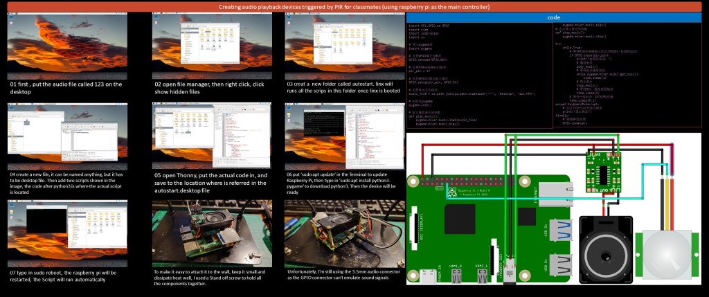
01 first , put the audio file called 123 on the desktop
02 open file manager, then right click, click show hidden files
03 creat a new folder called autostart. linx will runs all the scrips in this folder once linx is booted
04 create a new file, it can be named anything, but it has to be desktop file. Then add two scripts shown in the image, the code after python3 is where the actual script is located
05 open Thonny, put the actual code in, and save to the location where is referred in the autostart.desktop file
06 put ‘sudo apt update’ in the Terminal to update Raspberry Pi, then type in ‘sudo apt install python3-pygame’ to download python3. Then the device will be ready
07 type in sudo reboot, the raspberry pi will be restarted, the Script will run automatically
To make it easy to attach it to the wall, keep it small and dissipate heat well, I used a Stand off screw to hold all the components together.
Unfortunately, I’m still using the 3.5mm audio connector as the GPIO connector can’t emulate sound signals
import RPi.GPIO as GPIO
import time
import subprocess
import os
# 导入pygame库
import pygame
# 设置GPIO模式为BCM
GPIO.setmode(GPIO.BCM)
# 设置PIR传感器的引脚号
pir_pin = 17
# 设置GPIO引脚为输入模式
GPIO.setup(pir_pin, GPIO.IN)
# 设置音乐文件路径
music_file = os.path.join(os.path.expanduser(“~”), “Desktop”, “123.MP3”)
# 初始化pygame
pygame.init()
# 定义播放音乐的函数
def play_music():
pygame.mixer.music.load(music_file)
pygame.mixer.music.play()
pygame.mixer.music.play()
# 定义停止音乐的函数
def stop_music():
pygame.mixer.music.stop()
try:
while True:
# 等待PIR传感器输出状态为HIGH(检测到运动)
if GPIO.input(pir_pin):
print(“检测到运动!”)
# 播放音乐
play_music()
# 等待音乐播放完成
while pygame.mixer.music.get_busy():
time.sleep(1)
# 停止音乐
stop_music()
# 等待5秒,避免重复触发
time.sleep(5)
# 等待一段时间,降低CPU负载
time.sleep(0.1)
except KeyboardInterrupt:
# 当按下Ctrl+C时退出脚本
print(“退出脚本”)
finally:
# 清理GPIO设置
GPIO.cleanup()
Final Installation in Exhibition Space
In the final stage of installation I borrowed a Japanese demon named Nurikabi as the inspiration for my work within the space. This monster is said to often turn into an invisible wall, disorientating people who are out in the wild and causing them to keep circling around a particular area. It is not until these people feel a sense of vestige that they realise it is the demon performing mischievous acts.
I used this demon as my inspiration for a number of reasons. Firstly, I consider myself to be very fortunate, both in terms of furthering my education and in terms of living a life that embodies a bizarre kind of luck. I can’t think of any reason for this cause either, and even if I did find one, it would be just a theoretical loop of logic. That’s why I came across Nurikabi when I was thinking about my life, and secondly, when I was creating something, I was always able to connect it to my initial thoughts and ideas, and it was hard to make a new breakthrough. This is my Nurikabi in terms of creative thinking, and in terms of life, I feel that the state of my graduation from this school is very similar to the state of my graduation from London, both of them have some kind of fear of the society, and this sense of fear has become my Nurikabi in terms of life.
Final Installation in Exhibition Space Video:
Appearance: Little is known about the true appearance of nurikabe because these yokai are usually said to be invisible. During the Edo period, however, artists began to illustrate this creature, giving it an appearance somewhere between a grotesque, fantastic beast and a flat, white wall. Modern representations of the nurikabe depict it as a plain, gray, bipedal wall with vague face-like features.
Behavior: Nurikabe appear mysteriously on roads late at night. As a traveler is walking, right before his or her eyes, an enormous, invisible wall materializes and blocks the way. There is no way to slip around this yokai; it extends itself as far as to the left and right as one might try to go. There is no way over it either, nor can it be knocked down. However, it is said that if one taps it near the ground with a stick, it will vanish, allowing the traveler to continue on his or her way.
